
STEM OnLine mini dictionary
STEM OnLine mini dictionary
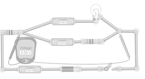
Basic mixed electric circuit
This simulation shows a circuit with one series resistance and two parallel branches: one with a resistor and the other with a bulb. Ammeters let you see how the current is the same in the series section and divides when it reaches the parallel branches. The voltmeter lets you check that the voltage is the same in both branches and measure the drop across the series resistance. This is a brief and clear activity to introduce how series and parallel combine in a mixed circuit.

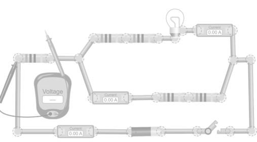
Circuit with two parallel branches with internal series sections
This simulation presents a mixed circuit consisting of an external series resistance and two parallel branches with different internal configurations. One branch contains a bulb and two resistors in series, creating a path with a high total resistance. The other branch has two resistors in series, forming a simpler path but with its own resistance to current flow. This difference between branches allows you to see how the current divides unevenly in the parallel section, since each path offers a different total resistance. Ammeters let you compare the current in each section, while the voltmeter lets you measure the voltage between different points in the circuit. This setup is designed to help you understand how several levels of series and parallel can be combined within a single mixed circuit and how each section affects the overall behavior.
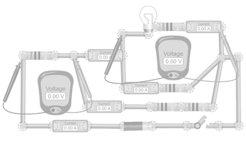
CCircuit with two parallel branches with internal series sections
This simulation presents a mixed circuit consisting of an external series resistance and two parallel branches with different internal configurations. One branch contains a bulb and two resistors in series, creating a path with a high total resistance. The other branch has two resistors in series, forming a simpler path but with its own resistance to current flow. This difference between branches allows you to see how the current divides unevenly in the parallel section, since each path offers a different total resistance. Ammeters let you compare the current in each section, while the voltmeter lets you measure the voltage between different points in the circuit. This setup is designed to help you understand how several levels of series and parallel can be combined within a single mixed circuit and how each section affects the overall behavior.
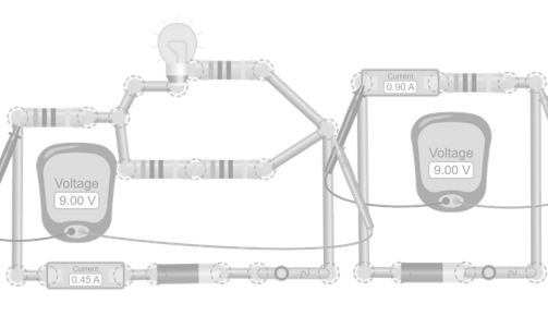
Comparison between a mixed circuit and its equivalent resistance
This simulation presents two circuits placed side by side to directly observe how the equivalent resistance formulas work in mixed circuits. The first circuit includes an external resistance and two parallel branches, each with its own total resistance. The second circuit is much simpler: it contains only a single resistor, whose value can be adjusted to match the equivalent resistance calculated from the mixed circuit. This setup allows you to see that, when the resistance of the simple circuit matches the equivalent resistance of the complex circuit, both show the same total current for the same applied voltage. This activity is designed to experimentally verify that different internal configurations can behave electrically equivalent when their total resistance is the same, reinforcing the concept of equivalence between circuits.


View product