
STEM OnLine mini dictionary
STEM OnLine mini dictionary
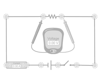
Power calculation in a resistor
This simulation allows you to check that the power absorbed by a resistor is not a fixed value, but the result of two inseparable factors: on one hand, the circuit conditions—especially the applied voltage—and on the other, the characteristics of the component itself, represented by its resistance value. By modifying the voltage and observing how the current and power change, the student understands that the energy dissipated by a resistor depends simultaneously on the electrical environment in which it is connected and its resistance, which explains why different components heat up differently even under the same voltage.

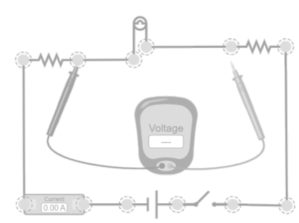
Power distribution in series
This simulation analyzes how power is distributed among several resistors connected in series when a voltage is applied to the set. The student observes that, since the same current flows through all of them, the power absorbed by each resistor depends on its value: higher-value resistors dissipate more power and, therefore, heat up more. Comparing the voltage drops and individual powers makes it clear that the energy distribution in the circuit is not uniform but is determined simultaneously by the series configuration and the characteristics of each component.
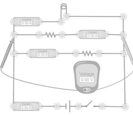
Power distribution in parallel
This simulation shows how power is distributed among several resistors connected in parallel when all are subjected to the same voltage. The student observes that, since the voltage is common to all branches, the power absorbed by each resistor depends directly on its value: smaller resistors allow more current to flow and therefore dissipate more power. Comparing the currents in each branch and the individual powers, it becomes clear that the energy distribution is not uniform but is determined simultaneously by the parallel configuration and the characteristics of each component, which helps to understand why some branches heat up more than others under the same voltage.
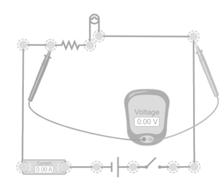
Losses in the Circuit
This simulation analyzes a simple circuit made up of an ideal voltage source, cables (which in this case are considered to have appreciable resistance—use the advanced menu on the right side of the screen for this), and a load connected at the end of the path. By including the resistance of the conductors, the student observes that part of the power delivered by the source does not reach the load entirely, but is dissipated in the cables themselves as heat. Comparing the total power supplied, the power actually received by the load, and the power lost in the conductors, it becomes clear that every real circuit presents inevitable losses and that efficiency depends both on the resistance of the load and the distributed resistance in the wiring.


View product