

Parallel circuits
The online parallel circuit simulations on this page allow you to interactively understand how current, voltage, and equivalent resistance behave in a simple circuit. Through virtual setups with a power source, switch, bulbs, resistors, ammeters, and voltmeters, you can check the relationship between the circuit current, resistance values, and voltage drops at different points.
This Thematic Unit is part of our Circuits collection

STEM OnLine mini dictionary
Branch
Portion of a circuit between two consecutive nodes containing one or more components.
Branch Independence
Property of parallel circuits where the failure or disconnection of a component in one branch does not affect the operation of the others.
Current Divider
Configuration of parallel branches that distributes the total source current inversely proportional to the resistance of each branch.
Equivalent Resistance
A single resistance that could replace all those in the circuit producing the same effect; in series, it is the sum of all of them.
Parallel Circuit
Configuration where components are connected to the same nodes, sharing the same voltage but splitting the current.
Voltage (Tension)
Electric potential difference between two points in a circuit that drives the movement of charges, measured in Volts (V).
What are parallel electric circuits
Parallel circuits are characterised by their components being connected in such a way that they form multiple branches, each with its own path for current. In this type of setup, the voltage across each branch is the same, whilst the total current from the source is divided among the different branches according to the value of their resistances. The equivalent resistance is obtained by summing the reciprocals of each connected resistance. Parallel circuits are a basic and straightforward configuration that forms the foundation for analysing more complex arrangements.
Formula for equivalent resistance
When several resistors are connected in parallel, their combined effect on the circuit can also be expressed as a single equivalent resistance. In this case, the equivalent resistance is found by summing the reciprocals of each connected resistance, using the following formula:
1/Req = 1/R1 + 1/R2 + 1/R3 +…+ 1/Rn
The voltage applied to each branch is the same, whilst the total circuit current is shared among the different branches according to their respective resistance values. In this way, the equivalent resistance represents the total opposition to the flow of current in a circuit with multiple available paths.
Practical example
Suppose we have three resistors connected in parallel with values of 10 Ω, 20 Ω, and 30 Ω. The equivalent resistance of the circuit is found by adding the reciprocals of each resistance:
1/Req = 1/10 + 1/20 + 1/30 = 0,100 + 0,050 + 0,033 = 0,183
Req = 1/0,183 = 5,46 Ω
This means that, from the perspective of the power supply, the set of resistors behaves as a single resistance of approximately 5.46 Ω. The voltage applied to each branch is the same, whilst the total current supplied by the source is divided among the three resistors according to their values. For example, if the source provides 12 V, the currents will be 1.2 A through the 10 Ω resistor, 0.6 A through the 20 Ω resistor, and 0.4 A through the 30 Ω resistor, which adds up to a total of 2.2 A.

STEM OnLine mini dictionary
Branch
Portion of a circuit between two consecutive nodes containing one or more components.
Branch Independence
Property of parallel circuits where the failure or disconnection of a component in one branch does not affect the operation of the others.
Current Divider
Configuration of parallel branches that distributes the total source current inversely proportional to the resistance of each branch.
Equivalent Resistance
A single resistance that could replace all those in the circuit producing the same effect; in series, it is the sum of all of them.
Parallel Circuit
Configuration where components are connected to the same nodes, sharing the same voltage but splitting the current.
Voltage (Tension)
Electric potential difference between two points in a circuit that drives the movement of charges, measured in Volts (V).
Explore the exciting STEM world with our free, online, simulations and accompanying companion courses! With them you’ll be able to experience and learn hands-on. Take this opportunity to immerse yourself in virtual experiences while advancing your education – awaken your scientific curiosity and discover all that the STEM world has to offer!
Parallel circuit simulations
Constant voltage
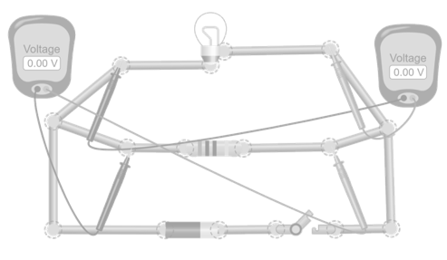
In this simulation, a circuit is built with a source, a switch, and a bulb and a resistor connected in parallel. A voltmeter is placed in each branch of the circuit to check that the voltage is the same in all of them and that it also matches the battery voltage. Change the resistance values and the battery voltage to verify that this property always holds in parallel connections.
Current distribution in parallel circuits
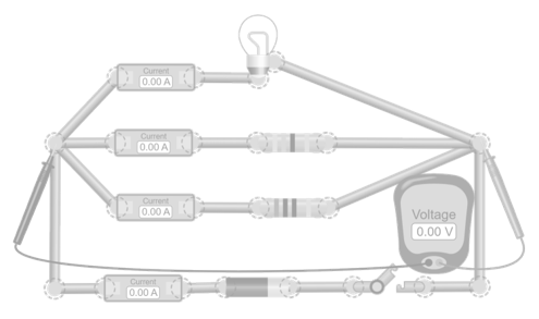
In this simulation, a circuit is built with a source, a switch, a bulb, and several resistors connected in parallel. A voltmeter is placed across the ends of the resistors. Additionally, ammeters are used in each branch and at the output of the source. Observe how the total current supplied by the battery is shared among the resistors in proportion to their value and how the sum of the partial currents matches the total current supplied by the source. Change the resistance values and the battery voltage to verify that this rule always holds.
Equivalent resistance in a parallel circuit
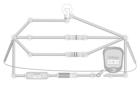
In this simulation, a circuit is constructed with a source, a switch, a bulb, and several resistors connected in parallel. A voltmeter is placed across the ends of the resistors and an ammeter to measure the total current supplied by the source. Calculate the equivalent resistance by measuring the total current and applying Ohm’s law (Req = V/I). Verify that the value obtained matches the result of adding the reciprocals of the individual resistances. Modify the resistance values and battery voltage to check that the rule always holds.
Branch independence
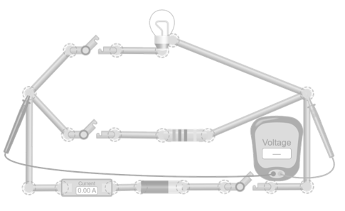
In this simulation, a circuit is built with a source, a main switch, and two branches connected in parallel: one with a bulb and another with a resistor. Each branch has its own switch. Observe how, when opening or closing any of the branch switches, the other continues to operate normally. The voltage in each branch remains constant, and only the total current supplied by the source changes. Change the resistance values and battery voltage to see how the total current varies without affecting the independent operation of each branch.
Giants of science
“If I have seen further, it is by standing on the shoulders of giants”
Isaac Newton
Michael Faraday
–
André-Marie Ampère
–
Become a giant
Principles of Modeling, Simulations, and Control for Electric Energy Systems
Principles of Electric Circuits | 电路原理
Electrotechnique I
Electromagnetic Compatibility Essentials
Professional development for Educators
Teach teens computing: Developing your programming pedagogy
Teaching with Physical Computing: Assessment of Project-Based Learning
Teach kids computing: Computing systems and networks
Teach teens computing: Impact of technology
Giants of science
“If I have seen further, it is by standing on the shoulders of giants”
Isaac Newton
Michael Faraday
–
James Clerk Maxwell
–
Become a giant
Principles of Modeling, Simulations, and Control for Electric Energy Systems
Principles of Electric Circuits | 电路原理
Electrotechnique I
Electromagnetic Compatibility Essentials
Professional development for Educators
Advancing Learning Through Evidence-Based STEM Teaching
HP Digital Skills for Educators – Google Workspace
Teach computing: Physical computing with Raspberry Pi and Python
Introduction to Online Education & Course Planning
Test your knowledge
What is a parallel circuit?
How do current and voltage behave in a parallel circuit?
Why do other components keep working if one fails in a parallel circuit?
Why do components in parallel not affect each other’s brightness or performance?
Where are parallel circuits used in real life?
You may also be interested
Last simulations
To learn and experience
Take your knowledge to the next level with science kits and hands-on tools that connect theory with experimentation
Relativity and Quantum Physics For Beginners

Teachers essentials
Notion
Organize your notes, tasks, and projects in one place. Notion combines notes, lists, and calendars in one flexible space.
Canva
Design presentations, diagrams, and infographics with easy-to-use templates and professional results
Genially
Create interactive content, presentations, and educational games in a simple and visual way
Desmos
The most intuitive graphing calculator to explore mathematics and create dynamic classroom activities
Tinkercad
Design in 3D and simulate electronic circuits for free; it’s the perfect tool for simple robotics projects
Your Infinite Library
Enjoy the freedom to explore millions of titles and a curated selection of magazines on any device
Join Prime for students and young adults
The best series. Millions of songs. All included with your subscription.
Science made fun
Learn with the best courses
edX
Online courses from leading universities and companies. Learn practical skills and earn professional certifications
Coursera
Courses from leading universities and companies. Learn practical skills and earn professional certifications
Udemy
Thousands of online courses tailored to your level. Learn at your own pace with expert instructors