
STEM OnLine mini dictionary
STEM OnLine mini dictionary
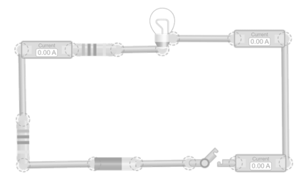
Constant current
In this simulation, a circuit is built with a power source, a switch, a light bulb, and several resistors connected in series. Several ammeters are placed at different points in the circuit to check that all register the same current value. Notice how, no matter how many resistors are added or what their values are, the current that flows is always the same throughout the path. Change the values of the resistors and the battery voltage to verify that this property always holds in series connections.

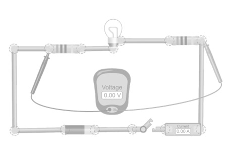
Equivalent resistance in a series circuit
In this simulation, a circuit is built with a power source, a switch, a light bulb, and several resistors connected in series. An ammeter is placed anywhere in the circuit and a voltmeter is placed across the resistors. Calculate the equivalent resistance by measuring the total voltage and applying Ohm’s Law (Req = V/I). Check that the result matches the sum of the individual resistances. Modify the values of the resistors and the battery voltage to see that this rule always applies.
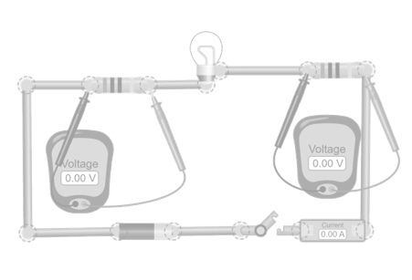
Voltage distribution in series circuits
In this simulation, a circuit is built with a power source, a switch, a light bulb, and several resistors connected in series. An ammeter is placed in series with the power source to measure the current. Additionally, voltmeters are used across each resistor and across the complete set. Observe how the total battery voltage is divided among the resistors in proportion to their values, and how the sum of the partial voltage drops matches the total applied voltage. Change the values of the resistors and the battery voltage to verify that this rule is always fulfilled.


View product