
STEM OnLine mini dictionary
STEM OnLine mini dictionary
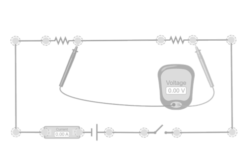
Basic voltage divider
In this simulation, the simplest voltage divider is represented: two resistors connected in series to a voltage source. The current flowing through both resistors is the same, so the voltage drop across each depends only on its value. The output voltage is taken at the intermediate point of the divider, between the two resistors. By changing the values of the resistors, you can observe how the output voltage changes. If you increase the lower resistor, the output voltage increases; if you decrease it, the output voltage drops. This behaviour directly reflects the relationship between the resistors in the divider.

Voltage divider with potentiometer
This simulation is the same as the basic voltage divider, but with a slightly different aim. As there is no element that simulates a real potentiometer with a sliding cursor, the behaviour of a potentiometer has been simulated by again using two resistors in series, manually adjusting both values in a complementary way so that their sum remains constant, as would happen in a potentiometer. The intermediate point between the two resistors acts as the potentiometer’s cursor. It is, therefore, a particular case of the basic voltage divider. By changing the values of R1 and R2 while keeping their sum fixed, the voltage measured at the intermediate node shifts continuously between 0 V and the source voltage, thus reproducing the behaviour of a voltage divider with potentiometer.
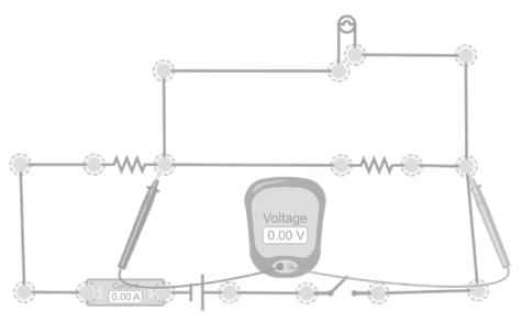
Voltage divider with connected load
This simulation analyses what happens when a load is connected to the output of a voltage divider. The load is placed in parallel with the lower resistor of the divider, so the equivalent resistance decreases and the output voltage is reduced compared to the ideal value. This phenomenon, known as the loading effect, is fundamental to understanding why a voltage divider only works properly when the load has a much higher resistance than the divider itself. Check that the output voltage decreases when the load is connected, in accordance with the equivalent resistance of the loaded divider.
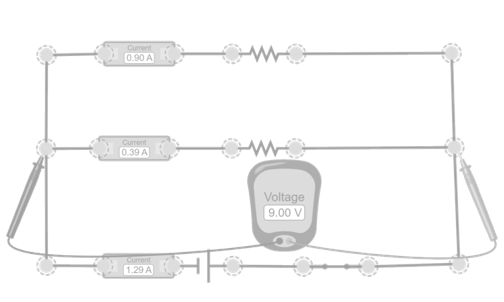
Current divider in parallel
In this simulation, it is studied how the current is distributed when two resistors are connected in parallel. In a parallel circuit, the voltage is the same across all branches, so the current flowing through each depends only on its resistance. Branches with lower resistance conduct more current, while those with higher resistance conduct less. This behaviour forms the current divider, which is complementary to the voltage divider. Check that the current in each branch matches the prediction of the current divider.


View product