Generic selectors
Exact matches only
Search in title
Search in content
Post Type Selectors

Thevenin’s theorem

16/04/2026

The online Thevenin theorem simulations on this page allow you to interactively explore how any electrical network, no matter how complex, can be replaced by a much simpler model—the Thevenin equivalent circuit—without altering the behavior seen from the load. Through a comparative setup—an original circuit with multiple sources and resistors versus its Thevenin equivalent made up of only a source and a resistor in series—you can experimentally determine the values of and , verify that both circuits deliver exactly the same voltage and current to the load, and confirm that this equivalence remains valid even when you change the circuit parameters. These simulations complement the theory and help you intuitively visualize the scope and practical usefulness of the Thevenin theorem.

What is the Thevenin theorem

The Thevenin theorem states that any linear network viewed from two terminals can be replaced by a much simpler circuit, the Thevenin equivalent circuit, consisting of only an equivalent voltage source and a series resistor. This transformation does not alter the electrical behavior observed by the load: the voltage, current, and power it receives remain exactly the same. The goal is to have a more manageable representation that allows us to analyze, understand, and predict the circuit’s operation without needing to work with all its internal complexity.

Open-circuit voltage (VTh)

is the voltage across the network between the two terminals where the load will be connected when no current is flowing. In that condition, the circuit displays its “pure internal voltage,” without drops due to resistances or dissipative elements. That’s why it’s interpreted as the equivalent electromotive force with which the network pushes outward: it’s the potential difference the network tries to impose at the terminals before any load modifies its behavior. From the load’s point of view,it’s the maximum voltage it could receive, because with no current there is no internal loss.

To determine this value in practice, the load is disconnected and the voltage between the terminals is measured or calculated with the circuit open. Since the current is zero in that situation, the observed voltage matches exactly the equivalent voltage source of the Thevenin model. That value, , is used to replace the entire network with a single ideal source in the equivalent circuit.

Equivalent resistance seen from the terminals (RTh)

represents the effective resistance offered by the network toward the two terminals where the load will be connected. It’s not a specific physical resistor, but rather the overall resistive behavior presented by the circuit when viewed from the outside. This resistance summarizes how all the passive elements are internally combined and how the sources influence the system’s response. From the load’s perspective,it determines how much voltage drop will occur when current flows and thus affects the final current and transferred power.

To obtain in practice, the action of internal sources is eliminated: ideal voltage sources are replaced by a short circuit and ideal current sources by an open circuit. This step does not change the passive structure of the circuit, but it does neutralize any energy contributions that would distort the resistance measurement. Once the sources are nullified, the equivalent resistance between the two terminals is calculated. That value is, and it’s used in the Thevenin model to represent how the network limits current when a real load is connected.

Application of the Thevenin Equivalent to a Load

Once VTh and RTh have been determined, the entire network can be replaced by its Thevenin equivalent without the load noticing any difference. When the load is connected to this simplified model, the voltage, current, and power it receives are exactly the same as in the original circuit, because the equivalent reproduces the voltage-current relationship that the network establishes at its terminals.

The analysis becomes immediate: the current depends only on VTh, RTh, and the load resistance, and the voltage across the load is obtained using a simple divider. This allows you to see how the system’s behavior changes when you modify the load, evaluate the transferred power, or identify matching conditions without recalculating the entire internal network. In essence, the Thevenin equivalent turns a complex circuit into an elementary one, while keeping the response experienced by the load unchanged.

Importance of the Thevenin Theorem

The Thevenin theorem is fundamental because it allows any linear network to be replaced by a simple model that exactly preserves the response experienced by the load. This reduction makes analysis easier, speeds up calculations, and lets you clearly study how load changes affect the circuit’s behavior. Thanks to this equivalence, complex problems become basic configurations that keep the essential information of the system intact.

Explore the exciting STEM world with our free, online, simulations and accompanying companion courses! With them you’ll be able to experience and learn hands-on. Take this opportunity to immerse yourself in virtual experiences while advancing your education – awaken your scientific curiosity and discover all that the STEM world has to offer!

Thevenin’s theorem simulations

Thevenin equivalent circuit


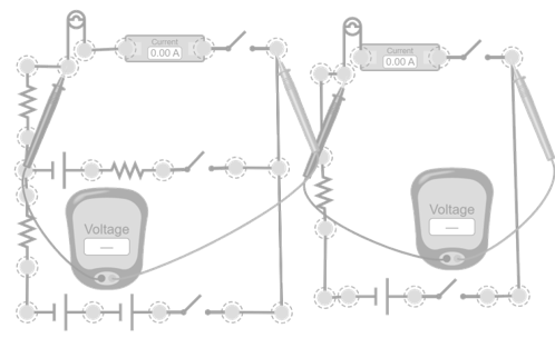
This simulation demonstrates how any circuit, no matter how complex, can be replaced by its Thevenin equivalent. Two setups are presented: on the left, the “original” circuit, consisting of several power sources and multiple resistors, with a load represented by a light bulb; on the right, its Thevenin equivalent, made up of only a voltage source and a resistor in series, with the same load connected to its terminals. The exercise consists of practically determining the values of and . First, leave both loads open-circuited and adjust the voltage of the equivalent circuit’s source until the voltmeter readings match in both setups. This adjusted value corresponds to . Next, close the circuit so current flows through the bulbs and change the resistance of the equivalent until the measured currents are equal in both cases. The final value of that resistance is . Additionally, you can freely change the values of the batteries, resistors, or the load itself and verify that, regardless of the configuration of the original circuit, it’s always possible to readjust the source and resistance of the Thevenin equivalent to reproduce exactly the same behavior in the load. You can even build a different circuit and check that you can find its Thevenin equivalent.
Licencia de Creative Commons

“If I have seen further, it is by standing on the shoulders of giants”

Isaac Newton

Your path to becoming a giant of knowledge begins with these top free courses

Test your knowledge

You may also be interested

Cargando clima y ubicación...

You may also be interested

Created by potrace 1.15, written by Peter Selinger 2001-2017