Generic selectors
Exact matches only
Search in title
Search in content
Post Type Selectors

Combination of AC sources

11/09/2026

The online AC source combination simulations on this page allow you to immediately see how two alternating signals behave when they act together within a real circuit. To do this, we build two simple setups, one in series and one in parallel, each with its own light bulb as a visual indicator and with the necessary instruments to measure what happens. The voltmeter is always placed between the main nodes to show the voltage received by the bulb, while the ammeter is placed at the appropriate point to record the current flowing. From there, the visitor can modify the source parameters and observe how the brightness, voltage, and current change, directly understanding the superposition of AC signals without resorting to calculations.

This Thematic Unit is part of our Circuits collection

STEM OnLine mini dictionary

Beat

A dynamic phenomenon that appears when alternating current sources with slightly different frequencies are combined, characterized by a periodic fluctuation of the total amplitude that creates a visual modulation or envelope pattern.

Circulating current

An undesired electrical current that flows directly between two power sources connected in parallel when there is a mismatch in voltage, phase, or frequency, potentially causing instability or severe damage to the equipment.

Constructive interference

An effect that occurs when two or more alternating current waves coincide in phase or with minimal phase shift, causing their instantaneous amplitudes to add up and result in a signal with a higher total voltage or current.

Destructive interference

An effect that occurs when two alternating current waves are out of phase, causing their instantaneous amplitudes to subtract from each other, thereby reducing the total magnitude of the electrical signal or distorting its original shape.

Overlap distortion

An undesired alteration in the original geometric shape of an electrical signal within electronic circuits, produced when multiple alternating current waves interact unfavorably at a common node of the circuit.

Signal envelope

An imaginary curve outline connecting the peak and trough values of a complex or modulated waveform, making visible the periodic amplitude variation pattern caused by phenomena such as frequency beats.

Source combination

The connection of multiple alternating current generators within the same electrical circuit to analyze the superposition of their signals. The final output of voltages and currents depends simultaneously on the amplitudes, frequencies, and phase relationships of each source.

Source synchronization

A mandatory process in electrical engineering that involves matching the frequency, phase, and amplitude of two or more generators before connecting them in parallel. This prevents destructive circulating currents between the sources.

Vector signal summation

A mathematical and geometrical method used in electronics to combine alternating current signals, taking into account both the magnitude of the waves and their respective phase angles, rather than performing a simple arithmetic addition.

Wave superposition

A physical and electrical phenomenon where two or more sine waves combine at every instant of time within a circuit, resulting in a new composite waveform that can exhibit reinforcement, attenuation, or cancellation.

Ad

What is the combination of AC sources

The combination of AC sources consists of connecting two or more alternating current sources within the same circuit to observe how their electrical effects add up. When multiple sources act simultaneously, their voltages and currents do not add up in a simple way: they depend on the amplitude, frequency, and, above all, the phase of each one.

In an AC circuit, each source generates a sinusoidal wave. When combined, these waves overlap and produce results that can be very different from those of each source individually: amplitude increases, reductions, partial or total cancellations, and even periodic variations when the frequencies are different.

Understanding how multiple AC sources interact is fundamental to interpreting real phenomena such as interference, current distribution, beats, or unexpected behaviors in electrical grids. Simulations allow for the immediate visualization of this superposition and for understanding how small changes in phase or frequency completely modify the final result.

AC sources in series

When two AC sources are connected in series, their voltages add up following the rules of superposition. However, this sum is not arithmetic: it depends on the amplitude, frequency, and phase of each source. If both waves are in phase, the resulting voltage increases; if they are out of phase, the combination may decrease or even cancel out. In this configuration, the current flowing through the circuit is the same for both sources, so any difference in phase or frequency is directly reflected in the total waveform. This allows for the observation of phenomena such as constructive interference, where voltages reinforce each other, and destructive interference, where they are attenuated.

Voltage summation

When two AC sources are connected in series, their voltages combine following the principle of superposition. The total circuit voltage is the instantaneous sum of the individual voltages, which means it depends on how the waves coincide at any given moment. If both sources have the same frequency and are aligned, the resulting voltage increases; if they are out of phase, the sum may be lower or even cancel out completely.

Influence of phase

Phase is the factor that most determines the result of the combination. Two sources with the same amplitude and frequency can produce very different voltages depending on the phase shift between them. A small phase shift produces a reinforced signal; a large phase shift can reduce the total amplitude. When the phase shift reaches 180°, the voltages completely oppose each other.

Constructive and destructive interference

Constructive interference appears when waves reinforce each other, increasing the amplitude of the total voltage. Destructive interference occurs when waves counteract each other, reducing the amplitude or distorting the waveform. In series, these effects are observed very clearly because the total voltage is the direct sum of both sources.

Phase cancellation

If two sources have the same amplitude and frequency but are 180° out of phase, the resulting voltage is practically zero. Although each source continues to generate its own wave, the instantaneous sum cancels out. This phenomenon is especially useful for understanding how phase can completely dominate circuit behavior.

Effect of different frequencies (beats)

When sources have slightly different frequencies, the total voltage shows a characteristic pattern: beats. The amplitude appears to grow and decrease periodically, creating an envelope visible in the simulation. This effect arises from the difference between the frequencies and is a direct demonstration of how wave superposition produces dynamic phenomena even in simple circuits.

AC sources in parallel

Connecting two AC sources in parallel means joining them across the same two nodes of the circuit. In this configuration, the voltage is common to all sources because they share the exact same connection points. This implies that, in an ideal theory, all sources must have the same instantaneous voltage regardless of their internal characteristics. In real practice, connecting different AC sources in parallel is not physically viable if they are not perfectly synchronized. If each source tries to impose a different voltage, huge currents would flow between them, generating instability and potential damage. Therefore, in real-world installations, sources in parallel are only used when they are synchronized in frequency, phase, and amplitude, as is the case with generators in an electrical grid.

Current summation

In a parallel connection, each source attempts to impose its own current on the circuit. The total current is the instantaneous sum of the currents provided by each source, and this sum depends on how the waves coincide at any given moment. If the sources are in phase, the total current increases; if they are out of phase, the sum may decrease or even partially cancel out.

Influence of phase

Phase determines how the currents from each source interact. A small phase shift can modify the shape of the total current, while a large phase shift can cause one source to “push” current in the opposite direction to the other. When the phase shift reaches 180°, the currents completely oppose each other, generating a notable reduction in the total circuit current.

Constructive and destructive interference

Constructive interference appears when the currents of both sources reinforce each other, increasing the total current. Destructive interference occurs when the currents counteract each other, reducing the amplitude or distorting the waveform. In parallel, these effects are observed very clearly because each source contributes directly to the total current.

Phase cancellation

If two sources have the same amplitude and frequency but are 180° out of phase, the total current can approach zero. Although each source continues to generate its own current, the instantaneous sum cancels out. This phenomenon is especially useful for understanding how phase can dominate circuit behavior even when sources are connected in parallel.

Effect of different frequencies (beats)

When sources have slightly different frequencies, the total current shows the beat phenomenon: the amplitude of the current appears to grow and decrease periodically. The resulting envelope is very visible in simulations and demonstrates how the superposition of waves with different frequencies generates dynamic variations even in simple configurations.

Real-world applications of combining AC sources

Although the combination of AC sources is studied ideally in educational circuits, the phenomena of superposition, interference, and phase shift appear constantly in real electrical systems. In distribution networks, audio equipment, and electronic devices, different sources or signals interact with each other, producing reinforcements, cancellations, or waveform distortions. Understanding these effects helps interpret behaviors that might appear anomalous at first glance, but are a direct consequence of the superposition of alternating voltages and currents.

Interference in electrical networks

In an electrical network, several generators work in parallel to supply energy. If they are not perfectly synchronized in frequency and phase, small differences may appear that produce interference in the voltage or current. These variations can manifest as fluctuations, harmonics, or waveform distortions, especially when large loads are connected or disconnected. Coordination between generators is based precisely on preventing their voltages from combining unfavorably.

Audio systems and signal mixing

In audio, the combination of AC signals is constant. When two sound sources are mixed, their waves overlap and can reinforce or cancel each other depending on their phase. This explains phenomena such as vocal cancellation in some systems, phasing and flanging effects, or the appearance of beats when two tones have close frequencies. Although the context is acoustic, the mathematical behavior is identical to that of electrical sources.

Superposition in basic electronics

In electronic circuits, many AC signals are combined at common points: oscillators, modulators, filters, or amplification stages. The interaction between signals can produce interference, distortion, or amplitude variations that must be controlled to ensure the correct operation of the circuit. Wave superposition is the basis for phenomena such as vector summation of signals, the emergence of envelopes, or the generation of complex periodic patterns.


STEM OnLine mini dictionary

Beat

A dynamic phenomenon that appears when alternating current sources with slightly different frequencies are combined, characterized by a periodic fluctuation of the total amplitude that creates a visual modulation or envelope pattern.

Circulating current

An undesired electrical current that flows directly between two power sources connected in parallel when there is a mismatch in voltage, phase, or frequency, potentially causing instability or severe damage to the equipment.

Constructive interference

An effect that occurs when two or more alternating current waves coincide in phase or with minimal phase shift, causing their instantaneous amplitudes to add up and result in a signal with a higher total voltage or current.

Destructive interference

An effect that occurs when two alternating current waves are out of phase, causing their instantaneous amplitudes to subtract from each other, thereby reducing the total magnitude of the electrical signal or distorting its original shape.

Overlap distortion

An undesired alteration in the original geometric shape of an electrical signal within electronic circuits, produced when multiple alternating current waves interact unfavorably at a common node of the circuit.

Signal envelope

An imaginary curve outline connecting the peak and trough values of a complex or modulated waveform, making visible the periodic amplitude variation pattern caused by phenomena such as frequency beats.
Source combination

The connection of multiple alternating current generators within the same electrical circuit to analyze the superposition of their signals. The final output of voltages and currents depends simultaneously on the amplitudes, frequencies, and phase relationships of each source.

Source synchronization

A mandatory process in electrical engineering that involves matching the frequency, phase, and amplitude of two or more generators before connecting them in parallel. This prevents destructive circulating currents between the sources.

Vector signal summation

A mathematical and geometrical method used in electronics to combine alternating current signals, taking into account both the magnitude of the waves and their respective phase angles, rather than performing a simple arithmetic addition.

Wave superposition

A physical and electrical phenomenon where two or more sine waves combine at every instant of time within a circuit, resulting in a new composite waveform that can exhibit reinforcement, attenuation, or cancellation.

Explore the exciting STEM world with our free, online, simulations and accompanying companion courses! With them you’ll be able to experience and learn hands-on. Take this opportunity to immerse yourself in virtual experiences while advancing your education – awaken your scientific curiosity and discover all that the STEM world has to offer!

Ad

AC source combination simulations

AC sources in series


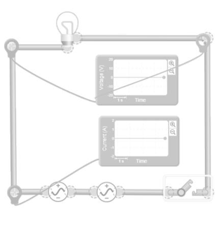
In this simulation, a circuit is built consisting of two alternating current sources connected in series and a light bulb at the end of the path. The light bulb acts as an immediate visual indicator; when the resulting voltage of the combination increases, the brightness increases, and when the combination is reduced or cancelled, the brightness decreases or disappears. This allows for an intuitive view of how the sum of voltages behaves in a series connection. To allow the visitor to measure what is happening, a voltmeter is placed across the light bulb terminals, showing the total voltage generated by the superposition of both sources. Additionally, an ammeter is installed in series with the circuit to record the current flowing through the light bulb and both sources. With these two instruments, the visitor can relate the brightness to the actual electrical values. The interaction involves modifying the source parameters (voltage, phase, and frequency) and observing how the total voltage and, consequently, the light bulb’s brightness change. When the sources are in phase, the voltage is reinforced and the bulb shines brighter. When a phase shift is introduced, the resulting voltage decreases. If the phase shift reaches 180°, the bulb practically turns off. If the frequencies are adjusted to be slightly different, the bulb displays a brightness that rises and falls periodically, reflecting the phenomenon of beats. The simulation graph allows you to see how the resulting waveform matches what the voltmeter, ammeter, and light bulb show.


Licencia de Creative Commons

AC sources in parallel


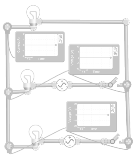
In this simulation, a circuit is built with two alternating current sources connected in parallel, sharing exactly the same two nodes. To visualize the effect of the combination, a light bulb is also connected between these nodes. Since the voltage is common to all branches, the light bulb acts as an indicator of the final result: if the currents provided by the sources reinforce each other, the bulb shines brighter; if they oppose each other, the brightness decreases. Although the voltage does not add up, the interaction between the currents modifies the power reaching the bulb, which is immediately reflected in its brightness. To measure what happens, a voltmeter is installed between the two main nodes, showing the common voltage shared by the sources and the bulb. Additionally, an ammeter is placed in one of the branches, so the user can see the current provided by each source and compare it with the total current flowing through the bulb. This setup allows for understanding that, in parallel, voltage remains fixed, but currents do change according to the phase and frequency of each source. The interaction consists of modifying the parameters of the sources and observing how the total current reaching the bulb varies. When the sources are in phase, both provide current in the same direction and the bulb receives more power, increasing its brightness. When a phase shift is introduced, part of the current from one source opposes the other, reducing the net contribution and causing the bulb to dim. If the phase shift reaches 180°, the total current can approach zero and the bulb barely lights up. If the frequencies are adjusted to be slightly different, the bulb shows a brightness that rises and falls periodically, reflecting the beats in the total current. The simulation graph allows relating these changes to the waveform actually flowing through the bulb.


Licencia de Creative Commons

“If I have seen further, it is by standing on the shoulders of giants”

Isaac Newton

Your path to becoming a giant of knowledge begins with these top free courses

Training programs aimed at strengthening educational practices in science and technology

Test your knowledge

Combining alternating current sources involves connecting two or more sinusoidal signals within the same circuit to observe how they superimpose. Although it might seem that their voltages or currents should add up directly, the result actually depends on the amplitude, frequency, and, above all, the phase of each source. Wave superposition produces reinforcement, cancellation, and deformation that do not appear when each source is analyzed separately. For this reason, the combination of AC sources is essential for understanding phenomena such as interference, beats, and unexpected behaviors in electrical grids and electronic systems.
The phase determines the point in the cycle at which each source is located at a specific instant, and it is the factor that most influences the result of the combination. Two sources with the same amplitude and frequency can produce a reinforced signal if they are aligned, or an almost canceled signal if they are one hundred and eighty degrees out of phase. This effect is observed both in series connections, where voltages are added, and in parallel, where currents are added. Phase controls whether waves support or counteract each other, and explains why small variations can completely transform the shape of the resulting signal.
When two AC sources in series have the same amplitude and frequency but are 180 degrees out of phase, each attempts to impose an opposite voltage at every instant. Although both generate their own wave, the instantaneous sum of their voltages cancels out, and the circuit effectively sees zero volts. This phenomenon, known as phase cancellation, shows how phase can dominate circuit behavior even when the sources are identical. It is a clear demonstration that in alternating current, knowing the amplitude is not enough: the synchronization between signals is equally important.
In a parallel connection, all sources share exactly the same nodes, which means they must impose the same instantaneous voltage. If each source attempts to impose a different voltage, enormous currents appear between them because each one “pushes” against the other. This can lead to instability, overheating, and equipment damage. For this reason, in real-world systems, sources in parallel are only used when they are perfectly synchronized in frequency, phase, and amplitude, as is the case with generators in an electrical grid. Theory allows for the study of the phenomenon, but practice requires strict coordination.
Beats are periodic variations in the amplitude of the resulting signal when two sources have frequencies that are very close but not identical. The superposition of both waves produces an envelope that grows and diminishes rhythmically, as if the signal were breathing. This effect is a direct consequence of the difference between the frequencies and appears in both series voltages and parallel currents. Beats are highly visible in simulations and help to understand how the combination of alternating signals can generate dynamic behaviors even in very simple circuits.

You may also be interested

Tools

Scientific calculator

Powered by Desmos

Scientific Dictionary

Powered by Wikipedia

2026 Best Online STEM Education Platform

Cargando clima y ubicación...

To learn and experience

Take your knowledge to the next level with science kits and hands-on tools that connect theory with experimentation

Essential for teachers and students

Learn with the best courses

Ad

You may also be interested