Frequency in AC Circuits. Behavior of R, L, and C
The online AC circuit frecuency simulations on this page allow you to observe how a resistor, a capacitor, and an inductor behave when the frequency of the AC signal driving them is changed. As the frequency increases or decreases, each component responds differently. The resistor always maintains the same current, the capacitor allows more current to pass at high frequencies, and the inductor does exactly the opposite. These simulations allow you to see directly how frequency affects the amplitude and phase of the current in each case, and why these three components are used to select, filter, or modify AC signals.
This Thematic Unit is part of our Circuits collection

STEM OnLine mini dictionary
Current Decay
Dynamic process in which the current decreases exponentially as the inductor releases stored energy.
Current Growth
Dynamic process in which the current increases exponentially from zero to the maximum value set by the resistance.
Inductor
Passive component that stores energy in the form of a magnetic field when an electrical current flows through it.
Magnetic Energy
Energy accumulated within the magnetic field generated by the inductor during the passage of electric current.
Parallel Inductors
Configuration where inductor terminals are connected to common points, decreasing the total equivalent inductance of the circuit.
RL Circuit
Electrical configuration consisting of a resistor and an inductor in which the current evolves gradually due to the coil’s opposition to sudden changes in flow.
Series Inductors
Configuration where coils are connected one after another, directly adding their values to obtain a higher equivalent inductance.
Steady State
Final equilibrium state where the current stabilizes and the inductor ideally behaves as a short circuit.
Time Constant
Temporal parameter calculated as the ratio of inductance to resistance that defines how quickly the current responds to circuit variations.
Transient Phase
Period of time in which the circuit’s current and voltages evolve along an exponential curve before stabilizing.
What Is Frequency in AC Circuits
Frequency is the number of complete cycles that an alternating signal completes in one second, and it is expressed in hertz (Hz). Each cycle includes all phases of the wave: the rising edge, the falling edge, and the change in direction. This seemingly simple quantity determines the rate at which voltage and current are continuously varying within the circuit. In alternating current, the signal does not remain constant: it causes the current to increase, decrease, and change direction over and over again, as many times per second as indicated by the frequency.
Although the definition of frequency can be reduced to “cycles per second,” its effect on an AC circuit is profound. It determines the current’s amplitude, the phase shift, the role of each component, and, ultimately, the circuit’s overall behavior in response to an alternating signal.
Reactance and impedance in AC circuits
This constant variation makes frequency the variable that controls how an AC circuit actually responds. Not all components can keep up with these changes equally well. A resistor always behaves the same way, because its resistance to current flow does not depend on the signal’s frequency. In contrast, a capacitor and an inductor do react differently when the signal oscillates faster or slower, because they store energy in an electric or magnetic field and need time to charge or discharge. When the frequency is low, they have that time; when it is high, the signal changes so quickly that their response changes significantly.
From this interaction between frequency and the response characteristics of each component, two fundamental concepts in AC emerge: reactance and impedance.
Reactance in an AC circuit
Reactance is the opposition to the flow of alternating current due exclusively to capacitors and inductors. It depends directly on frequency. Capacitive reactance decreases as frequency increases, while inductive reactance increases with frequency.
Impedance of an AC circuit
Impedance is the total opposition of the circuit and combines resistance—which dissipates energy—with reactance, which only stores and returns energy. Impedance determines both the amount of current flowing and the phase shift between voltage and current.
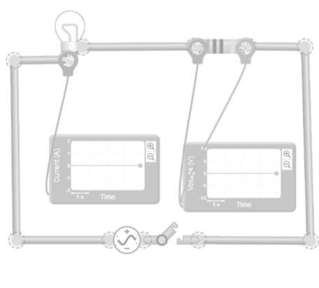
Resistor. Frequency-Independent behavior
A resistor behaves the same way in both direct current and alternating current because its resistance to the flow of current does not depend on the rate at which the signal changes direction. The resistor converts part of the electrical energy into heat, and its value remains constant regardless of how many cycles per second the signal has. Therefore, in an AC circuit, the current and voltage across a resistor are always in phase: when the voltage rises, the current rises; when the voltage falls, the current falls. It does not store energy, does not return energy, and does not introduce phase shift. Its role is purely dissipative and stable at any frequency.
In a pure resistor, the current responds instantaneously to any change in voltage. It does not need time to “charge” or “discharge” anything, because it does not store energy in any field. Therefore, in AC, the current and voltage reach their maximum and minimum values at the same time; they are in phase. The current waveform is an exact copy of the voltage waveform, simply scaled by the resistance value according to Ohm’s law. This direct and simultaneous relationship is what makes the resistor the simplest component to analyze in alternating current.
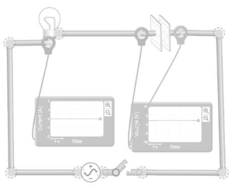
Capacitor. Frequency-Dependent behavior
A capacitor stores energy in the form of an electric field between its plates, and this ability to accumulate and release charge means that its AC behavior depends directly on the frequency. When the AC signal changes slowly, the capacitor has time to charge and discharge almost completely during each cycle, which limits the current. As the frequency increases, the voltage reverses direction before the capacitor has time to fully charge, and the resistance decreases. This relationship between the signal’s rate of change and the capacitor’s ability to keep up with it is the basis of its behavior in alternating current.
Effects of frequency change on a capacitor
The current in a capacitor depends on how quickly the voltage changes. At low frequencies, the voltage varies slowly and the capacitor charges easily, so the current is small. At high frequencies, the voltage changes so quickly that the capacitor is constantly adjusting its charge, resulting in larger currents. This effect is not arbitrary: the current is proportional to the rate of change of the voltage, so the faster the signal oscillates, the more current the capacitor draws in an attempt to keep up with it.
Capacitive reactance
The opposition a capacitor presents to the flow of alternating current is called capacitive reactance and is inversely proportional to frequency. At low frequencies, the reactance is high because the capacitor has time to fully charge and blocks the current. At high frequencies, the reactance decreases because the voltage changes direction before a significant charge can build up between the plates. This inverse relationship explains why a capacitor can behave almost like an open circuit at low frequencies and almost like a short circuit at high frequencies.
Frequency sweep of a capacitor
When a capacitor is analyzed using a frequency sweep, it can be observed that its reactance decreases progressively as the signal oscillates faster. In the low-frequency range, the current is minimal, and the capacitor barely allows any signal to pass through. As the frequency increases, the current grows, and the voltage drop across the capacitor decreases. In a wide-range sweep, this transition appears as a continuous slope that reflects the decrease in capacitive reactance. This response is essential for understanding filters, couplings, and any circuit in which a capacitor selects or attenuates specific frequencies.
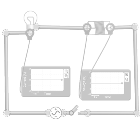
Coil. Frequency-Dependent behavior
A coil stores energy in the form of a magnetic field when current flows through it, and this ability to store and release energy means that its AC behavior depends directly on the frequency. When the AC signal changes slowly, the current has time to rise and fall without significant opposition. But as the frequency increases, the current attempts to change more rapidly, and the coil resists these changes, generating an induced voltage that limits the current. This relationship between the rate of change of the current and the induced voltage is the basis of the coil’s behavior in an alternating current circuit.
Effects of frequency change on a coil
The current in a coil depends on how quickly it tries to change. At low frequencies, the current changes slowly and the coil generates almost no induced voltage, so the resistance is small and the current can increase easily. At high frequencies, the current tries to change very quickly, and the coil responds by generating a voltage that opposes this change, thereby reducing the current. This effect causes the coil to allow less and less current to flow as the frequency increases, exhibiting behavior opposite to that of a capacitor.
Inductive reactance
The opposition that a coil presents to the flow of alternating current is called inductive reactance, and it increases with frequency. At low frequencies, the reactance is small because the current changes slowly and the induced voltage is minimal. As the frequency increases, the current attempts to change more rapidly, and the coil generates a greater voltage that opposes that change, thereby increasing the reactance. At very high frequencies, this opposition can become so great that the coil acts practically as an open circuit. This direct relationship between frequency and inductive reactance is fundamental to understanding its role in filters, choke coils, and AC response control.
Frequency sweep in a coil
During a frequency sweep, the coil exhibits an increasing response: at low frequencies, it allows current to flow easily, but as the frequency increases, the current decreases progressively. In the mid-frequency range, the voltage drop across the coil increases, reflecting the rise in inductive reactance. At high frequencies, the current decreases so much that the coil behaves almost like a blocking element. This continuous evolution is the characteristic signature of the coil in AC circuits and explains its use in circuits where the passage of fast signals needs to be attenuated or blocked.
The importance of frequency in AC circuits
Frequency is not just a signal parameter, but a tool that allows us to control how components—and, by extension, entire circuits—behave. In practice, frequency determines which part of a signal passes through, which is attenuated, and how energy is distributed among the circuit elements. For this reason, many electrical and electronic systems are designed with an eye toward how resistors, capacitors, and inductors react when the signal oscillates faster or slower.
In filtering applications, frequency determines which signals pass through a circuit and which are blocked. A capacitor passes high frequencies and attenuates low ones, while an inductor does exactly the opposite, allowing for the construction of high-pass, low-pass, or more complex filters. In power supply and power electronics systems, frequency influences efficiency and component size, since operating at higher frequencies allows for reducing the reactance of capacitors and increasing that of inductors as needed. In communications, frequency defines channels, bands, and the ability to transmit information without interference, taking advantage of the fact that each component responds differently depending on the signal’s frequency.
In all these cases, the principle is the same as the one studied in this unit: resistance remains constant, while the capacitor and inductor change their opposition to the flow of current as the frequency changes. This relationship makes it possible to select, shape, or limit signals, and makes frequency an essential variable in the design and operation of any alternating current circuit.

STEM OnLine mini dictionary
Current Decay
Dynamic process in which the current decreases exponentially as the inductor releases stored energy.
Current Growth
Dynamic process in which the current increases exponentially from zero to the maximum value set by the resistance.
Inductor
Passive component that stores energy in the form of a magnetic field when an electrical current flows through it.
Magnetic Energy
Energy accumulated within the magnetic field generated by the inductor during the passage of electric current.
Parallel Inductors
Configuration where inductor terminals are connected to common points, decreasing the total equivalent inductance of the circuit.
RL Circuit
Electrical configuration consisting of a resistor and an inductor in which the current evolves gradually due to the coil’s opposition to sudden changes in flow.
Series Inductors
Configuration where coils are connected one after another, directly adding their values to obtain a higher equivalent inductance.
Steady State
Final equilibrium state where the current stabilizes and the inductor ideally behaves as a short circuit.
Time Constant
Temporal parameter calculated as the ratio of inductance to resistance that defines how quickly the current responds to circuit variations.
Transient Phase
Period of time in which the circuit’s current and voltages evolve along an exponential curve before stabilizing.
Explore the exciting STEM world with our free, online, simulations and accompanying companion courses! With them you’ll be able to experience and learn hands-on. Take this opportunity to immerse yourself in virtual experiences while advancing your education – awaken your scientific curiosity and discover all that the STEM world has to offer!
AC circuit frecuency simulations
Ac power source with resistor
In this circuit, an AC source powers a resistor and a light bulb. The voltage and current rise and fall at exactly the same time, regardless of the frequency, demonstrating the characteristic behavior of a resistor in an AC circuit. The current is always in phase with the voltage.
In this unit, the simulation allows you to change the frequency of the source to observe what happens when the signal oscillates more slowly or more quickly. As the frequency increases or decreases, the current remains unchanged and the brightness of the light bulb stays constant, provided the resistance value remains the same. This allows you to directly verify that the resistance does not depend on frequency and that its behavior serves as a reference for comparison with the capacitor and the inductor, whose effects do vary when the frequency is changed.
AC power source with capacitor
In this circuit, an AC power source powers a capacitor and a light bulb. The voltage and current are no longer in phase because the capacitor needs to continuously charge and discharge, and that process changes the way the current flows. In this unit, you can change the frequency of the power source to see how the circuit responds. At low frequencies, the current is small and the light bulb barely glows because the capacitor charges almost completely during each cycle. At high frequencies, the current increases and the light bulb shines brighter because the voltage changes direction so quickly that the capacitor does not have time to fully charge and offers less resistance to the flow of current.
AC power source with inductor
In this circuit, an AC power source powers a coil and a light bulb. The coil resists rapid changes in current, so the current waveform no longer matches that of the voltage. In this unit, you can adjust the frequency of the power source to observe how the circuit responds. At low frequencies, the current changes slowly and the coil generates almost no induced voltage, so the light bulb glows normally. At high frequencies, the current tries to change very quickly, and the coil generates a voltage that opposes this change, reducing the current and causing the light bulb to glow less brightly. This simulation allows you to see directly how the coil offers increasing resistance to the flow of current as the frequency increases.
Comparison of amplitudes and phases in R, C, and L
In this simulation, a single alternating current source powers three independent branches: one with a resistor, another with a capacitor, and another with an inductor. Each branch receives exactly the same signal, allowing for a direct comparison of how each component responds when the source frequency is changed. As the frequency increases or decreases, you can observe how the current amplitude changes in each branch and how the phase difference between voltage and current varies. The resistor always keeps the current in phase and at a constant amplitude; the capacitor leads the current and allows more current to flow at high frequencies; and the inductor lags the current and allows less current to flow as the frequency increases. This simulation visually and simultaneously summarizes the fundamental differences between the three components in an alternating current circuit.
Giants of science
“If I have seen further, it is by standing on the shoulders of giants”
Isaac Newton
Michael Faraday
–
James Clerk Maxwell
–
Become a giant
Principles of Modeling, Simulations, and Control for Electric Energy Systems
Principles of Electric Circuits | 电路原理
Electrotechnique I
Electromagnetic Compatibility Essentials
Professional development for Educators
Teach Teens Computing: Understanding AI for Educators
STEM Outside
Learning How to Learn: Unlocking a Growth Mindset with AI
Teaching With Technology and Inquiry: An Open Course For Teachers
Giants of science
“If I have seen further, it is by standing on the shoulders of giants”
Isaac Newton
James Clerk Maxwell
–
Michael Faraday
–
Become a giant
Principles of Modeling, Simulations, and Control for Electric Energy Systems
Principles of Electric Circuits | 电路原理
Electrotechnique I
Electromagnetic Compatibility Essentials
Professional development for Educators
Teaching with Physical Computing: Introduction to Project-Based Learning
Learn Like a Pro: Science-Based Tools to Become Better at Anything
Reimagining higher education teaching in the age of AI
Innovating Instruction: Learning Design in the STEM Classroom
Test your knowledge
You may also be interested
Last simulations
To learn and experience
Take your knowledge to the next level with science kits and hands-on tools that connect theory with experimentation
Calculadora científica

Essential for teachers and students
Notion
Organize your notes, tasks, and projects in one place. Notion combines notes, lists, and calendars in one flexible space.
Canva
Design presentations, diagrams, and infographics with easy-to-use templates and professional results
Genially
Create interactive content, presentations, and educational games in a simple and visual way
Desmos
The most intuitive graphing calculator to explore mathematics and create dynamic classroom activities
Tinkercad
Design in 3D and simulate electronic circuits for free; it’s the perfect tool for simple robotics projects
Your Infinite Library
Enjoy the freedom to explore millions of titles and a curated selection of magazines on any device
Join Prime for students and young adults
The best series. Millions of songs. All included with your subscription.
Science made fun
Learn with the best courses
40% off!
Coursera
Courses from leading universities and companies. Learn practical skills and earn professional certifications
edX
Online courses from leading universities and companies. Learn practical skills and earn professional certifications
Udemy
Thousands of online courses tailored to your level. Learn at your own pace with expert instructors

