Generic selectors
Exact matches only
Search in title
Search in content
Post Type Selectors

Circuits with mixed sources (AC + DC)

11/09/2026

The circuit simulations with mixed sources (AC+DC) online on this page allow you to directly observe how a continuous signal and an alternating signal combine within a real circuit. Through the two proposed setups, the visitor can see how the resulting voltage affects the measured waveform, the current flowing, and the brightness of the bulb, and how the interaction between both sources depends on the way they are connected. These simulations offer a clear and visual way to understand the superposition of signals and the behavior of circuits that simultaneously use direct and alternating components.

This Thematic Unit is part of our Circuits collection

STEM OnLine mini dictionary

Beat

A dynamic phenomenon that appears when alternating current sources with slightly different frequencies are combined, characterized by a periodic fluctuation of the total amplitude that creates a visual modulation or envelope pattern.

Circulating current

An undesired electrical current that flows directly between two power sources connected in parallel when there is a mismatch in voltage, phase, or frequency, potentially causing instability or severe damage to the equipment.

Constructive interference

An effect that occurs when two or more alternating current waves coincide in phase or with minimal phase shift, causing their instantaneous amplitudes to add up and result in a signal with a higher total voltage or current.

Destructive interference

An effect that occurs when two alternating current waves are out of phase, causing their instantaneous amplitudes to subtract from each other, thereby reducing the total magnitude of the electrical signal or distorting its original shape.

Overlap distortion

An undesired alteration in the original geometric shape of an electrical signal within electronic circuits, produced when multiple alternating current waves interact unfavorably at a common node of the circuit.

Signal envelope

An imaginary curve outline connecting the peak and trough values of a complex or modulated waveform, making visible the periodic amplitude variation pattern caused by phenomena such as frequency beats.

Source combination

The connection of multiple alternating current generators within the same electrical circuit to analyze the superposition of their signals. The final output of voltages and currents depends simultaneously on the amplitudes, frequencies, and phase relationships of each source.

Source synchronization

A mandatory process in electrical engineering that involves matching the frequency, phase, and amplitude of two or more generators before connecting them in parallel. This prevents destructive circulating currents between the sources.

Vector signal summation

A mathematical and geometrical method used in electronics to combine alternating current signals, taking into account both the magnitude of the waves and their respective phase angles, rather than performing a simple arithmetic addition.

Wave superposition

A physical and electrical phenomenon where two or more sine waves combine at every instant of time within a circuit, resulting in a new composite waveform that can exhibit reinforcement, attenuation, or cancellation.

Ad

What are mixed-source circuits (AC + DC)?

Mixed-source circuits are those in which a direct current (DC) source and an alternating current (AC) source act simultaneously on the same circuit. By combining both signals, the DC component sets a base voltage or current level, while the AC component introduces a periodic variation around that level. The result is a signal that is neither purely alternating nor purely direct, but rather a superposition of both, with visible effects on light bulbs and measuring instruments.

Interaction of AC and DC signals in the same circuit

When a direct current (DC) signal and an alternating current (AC) signal coincide in the same circuit, the result is not an “intuitive mixture,” but a precise electrical interaction; each source attempts to impose its own condition on the nodes. The DC source establishes a fixed voltage level, while the AC source forces a periodic variation that is superimposed on that level. This combination produces a shifted, asymmetric signal with a non-zero mean value, which clearly modifies the behavior of light bulbs and measuring instruments.

Signal superposition

In a circuit with mixed sources, the resulting signal is not a new waveform created “halfway,” but the exact sum of what each source attempts to impose. The DC source fixes a constant voltage level, while the AC source adds a periodic variation on top of it. Mathematically, it is a sum; physically, the circuit nodes are subjected to both conditions simultaneously. This superposition is the reason why the final signal appears shifted, asymmetric, and with a non-zero mean value.

Displacement of the alternating wave by the DC component

When a DC source sets a voltage level in the circuit, the alternating signal stops oscillating around zero and begins to oscillate around that imposed level. This causes the sinusoidal wave to appear vertically shifted in voltmeter readings: the positive and negative parts are no longer symmetric. This shift does not change the frequency or shape of the AC wave, but it does modify its mean value and the way circuit elements respond, especially light bulbs, which exhibit a constant base brightness upon which the AC oscillation is superimposed.

Effects on voltage and current at the circuit nodes

The simultaneous presence of AC and DC clearly alters the electrical conditions of the nodes. The DC source fixes a stable potential difference, while the AC source forces that difference to rise and fall periodically. As a result, the voltage at the nodes ceases to be symmetric and acquires a non-zero mean value. The current flowing through the resistor or the light bulb also reflects this combination: it maintains a fixed component imposed by the DC and an oscillating component imposed by the AC. This dual nature explains the base brightness plus the visible vibration in the bulb and the shifted readings on measuring instruments.

Visible effects on light bulbs and measuring instruments

When a light bulb receives a DC component and an AC component simultaneously, its behavior is no longer a typical sinusoidal flicker. The DC component establishes a stable and constant base brightness, while the AC component introduces a periodic vibration on top of that level. Measuring instruments also reflect this mixture: the voltmeter shows a shifted and asymmetric signal, and the ammeter records a current with a non-zero mean value. All of this makes it possible to observe, very visually, how the presence of DC modifies the usual response of a circuit powered only by AC.

Average brightness and oscillation of the light bulb

The light bulb responds directly to the instantaneous power it receives. The DC component provides constant energy that maintains a fixed brightness, while the AC component causes that brightness to rise and fall periodically. The result is a light that never falls to zero but oscillates around a base level. The more DC voltage applied, the higher that level will be; the more AC amplitude added, the greater the visible oscillation.

Voltmeter readings in the presence of AC+DC

The voltmeter shows a signal that is no longer symmetric with respect to zero. The DC source shifts the alternating wave up or down, so that the positive and negative parts are no longer equivalent. The mean value of the reading increases or decreases according to the polarity of the DC, while the AC amplitude continues to mark the periodic variation. This reading is one of the clearest ways to visualize the superposition of signals.

Ammeter readings and current with a DC component

The ammeter records a current that combines two behaviors: a fixed component imposed by the DC and an oscillating component imposed by the AC. This means that the needle (or digital value) never returns to zero, but oscillates around a constant level. The presence of that DC component is what explains the base brightness of the bulb and the asymmetry of the signal measured in the circuit.

Applications of circuits with mixed AC+DC sources

Circuits that combine a DC source and an AC source appear in a multitude of electrical systems where it is necessary to superimpose a variable signal onto a fixed level. This mixture allows for the control of devices that require periodic excitation without losing a stable reference, and also makes it possible to transmit information, modulate signals, or adjust the behavior of elements sensitive to waveform. In lighting, the simultaneous presence of AC and DC is used to maintain a minimum brightness while introducing a periodic variation, and in power electronics, it allows for stabilizing the operation of loads that need a DC component to operate correctly. In instrumentation, AC+DC superposition is essential for shifting signals, calibrating sensors, or generating waveforms with a defined base level. In all these cases, the coexistence of both sources is not a side effect, but a deliberate tool to obtain a specific response from the circuit.


STEM OnLine mini dictionary

Beat

A dynamic phenomenon that appears when alternating current sources with slightly different frequencies are combined, characterized by a periodic fluctuation of the total amplitude that creates a visual modulation or envelope pattern.

Circulating current

An undesired electrical current that flows directly between two power sources connected in parallel when there is a mismatch in voltage, phase, or frequency, potentially causing instability or severe damage to the equipment.

Constructive interference

An effect that occurs when two or more alternating current waves coincide in phase or with minimal phase shift, causing their instantaneous amplitudes to add up and result in a signal with a higher total voltage or current.

Destructive interference

An effect that occurs when two alternating current waves are out of phase, causing their instantaneous amplitudes to subtract from each other, thereby reducing the total magnitude of the electrical signal or distorting its original shape.

Overlap distortion

An undesired alteration in the original geometric shape of an electrical signal within electronic circuits, produced when multiple alternating current waves interact unfavorably at a common node of the circuit.

Signal envelope

An imaginary curve outline connecting the peak and trough values of a complex or modulated waveform, making visible the periodic amplitude variation pattern caused by phenomena such as frequency beats.

Source combination

The connection of multiple alternating current generators within the same electrical circuit to analyze the superposition of their signals. The final output of voltages and currents depends simultaneously on the amplitudes, frequencies, and phase relationships of each source.

Source synchronization

A mandatory process in electrical engineering that involves matching the frequency, phase, and amplitude of two or more generators before connecting them in parallel. This prevents destructive circulating currents between the sources.

Vector signal summation

A mathematical and geometrical method used in electronics to combine alternating current signals, taking into account both the magnitude of the waves and their respective phase angles, rather than performing a simple arithmetic addition.

Wave superposition

A physical and electrical phenomenon where two or more sine waves combine at every instant of time within a circuit, resulting in a new composite waveform that can exhibit reinforcement, attenuation, or cancellation.

Explore the exciting STEM world with our free, online, simulations and accompanying companion courses! With them you’ll be able to experience and learn hands-on. Take this opportunity to immerse yourself in virtual experiences while advancing your education – awaken your scientific curiosity and discover all that the STEM world has to offer!

Ad

Circuit simulations with mixed sources (AC + DC)

AC and DC sources in series


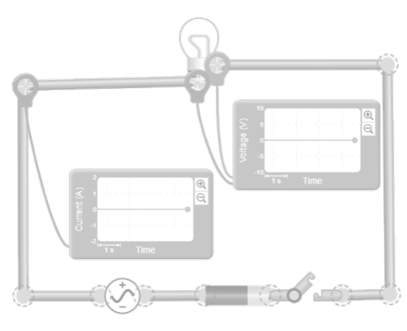
In this circuit, the alternating source and the direct source are connected in series along with the light bulb, forming a single loop. The entire assembly is controlled by a single master switch that opens or closes the current path through both sources and the bulb simultaneously. The voltmeter is connected in parallel with the light bulb to measure the voltage it receives, and the ammeter is placed in series with it to record the total circuit current. The user can modify the parameters of each source. By varying these parameters, the voltage reaching the bulb changes immediately; the direct component shifts the alternating wave vertically, and the alternating component introduces the periodic oscillation above that level. The visitor can observe how the measured waveform is transformed and how the brightness of the bulb responds to the combination of both sources.


Licencia de Creative Commons

AC and DC sources in parallel


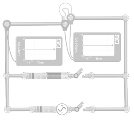
In this circuit, the alternating source and the direct source are connected in parallel, sharing the same two nodes. To prevent the sources from short-circuiting each other by imposing different voltages, each one incorporates a small series resistor. The light bulb is also connected between those two points, so it directly receives the combined voltage that the sources impose on the node. Each of the sources has its own switch that activates or deactivates it. The voltmeter is connected in parallel with the light bulb to measure the voltage it receives, and the ammeter is placed in series with it to record the current flowing through the light bulb. The user can modify the parameters of each source and activate or deactivate each one using their individual controls. By varying these settings, the node voltage changes immediately: the DC component sets the level around which the AC signal oscillates, and the AC component introduces the periodic variation around that level. The visitor can observe how the measured waveform shifts and deforms according to the combination of both sources, and how the brightness of the light bulb responds to the resulting voltage imposed by the two sources in parallel.


Licencia de Creative Commons

“If I have seen further, it is by standing on the shoulders of giants”

Isaac Newton

Your path to becoming a giant of knowledge begins with these top free courses

Training programs aimed at strengthening educational practices in science and technology

Test your knowledge

A circuit with mixed sources combines a continuous signal that sets a base voltage or current level with an alternating signal that introduces a periodic variation around that level. While it may seem like an intuitive mixture, it is actually an exact superposition: the DC source imposes a fixed condition on the nodes, and the AC source forces that condition to rise and fall periodically. The result is a shifted, asymmetric signal with a non-zero mean value, which clearly modifies the response of light bulbs, resistors, and measuring instruments.
The DC source establishes a stable voltage level, while the AC source adds an oscillation that is superimposed onto that level. This interaction causes the AC wave to stop oscillating around zero and instead oscillate around the value imposed by the DC. The resulting voltage appears offset in voltmeter readings, and the current combines a fixed component with an oscillating component. This dual nature explains the base brightness plus the periodic flicker in a light bulb and the asymmetry of the signals measured in the circuit.
The DC source sets a voltage level that acts as a reference for the entire signal. When the AC source is superimposed, its oscillation no longer occurs around zero, but around that imposed level. This causes the positive and negative parts of the wave to lose symmetry and the voltmeter to display a shifted signal. The frequency and shape of the AC wave do not change, but its vertical position does, which alters the average value and the way the circuit elements respond.
The light bulb responds to the instantaneous power it receives. The DC component provides stable energy that maintains a fixed brightness, while the AC component introduces a periodic oscillation on top of that level. That is why the light never drops to zero: it oscillates around a base brightness determined by the DC. The higher the DC voltage, the higher that level will be; the greater the AC amplitude, the more visible the superimposed vibration will be.
The ammeter measures the total current, which in a mixed circuit combines a fixed component imposed by the DC and an oscillating component imposed by the AC. This causes the reading to never return to zero, but rather to oscillate around a constant level. The presence of this DC component explains both the base brightness of the bulb and the asymmetry of the measured signal. It is one of the clearest ways to visualize how AC+DC superposition modifies the typical response of a circuit powered only by alternating current.

You may also be interested

Tools

Scientific calculator

Powered by Desmos

Scientific Dictionary

Powered by Wikipedia

2026 Best Online STEM Education Platform

Cargando clima y ubicación...

To learn and experience

Take your knowledge to the next level with science kits and hands-on tools that connect theory with experimentation

Essential for teachers and students

Learn with the best courses

Ad

You may also be interested