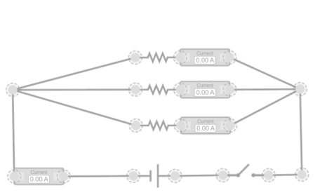
Kirchhoff’s Current Law (KCL)
In this simulation, we use for the first time the schematic representation of circuits, which shows the components using electrical symbols instead of drawings. This format is more suitable for analyzing nodes, branches, and loops, and will allow us to apply Kirchhoff’s Laws clearly and rigorously. In this simulation, a node is represented from which three branches with different resistances depart, all powered by the same source. An ammeter placed before the node measures the total current entering, while three other ammeters record the current flowing through each branch. When you change the values of the resistances or the source voltage, you can observe how the distribution of currents changes, but it always holds that the incoming current is equal to the sum of the outgoing currents. This direct visualization helps to intuitively understand Kirchhoff’s Current Law and shows that electric charge does not accumulate at the node, but is distributed among the various available paths. Check that the sum of currents measured at the node matches the prediction of Kirchhoff’s Current Law (KCL).

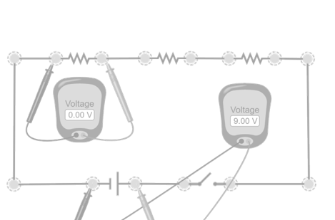
Kirchhoff’s Voltage Law (KVL)
In this simulation, a simple loop is built formed by a voltage source and several resistors connected in series. Using two voltmeters, you can measure the voltage drop across each resistor and check that their sum matches the total voltage supplied by the source. By changing the values of the resistors or the source voltage, you can see how the individual drops change, but it always holds that the algebraic sum of all voltages in the closed loop is zero. This experience allows you to directly visualize Kirchhoff’s Voltage Law and understand that the energy delivered by the source is distributed exactly among all elements of the loop. Check that the sum of the measured voltage drops in the loop matches the voltage from the source, as established by Kirchhoff’s Voltage Law (KVL).
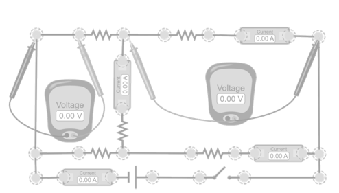
Double loop with shared node
In this simulation, a circuit is presented consisting of two loops that share a central resistor, which prevents it from being simplified using equivalent resistances. Each loop includes its own path with resistors, and both are connected at a common node. Ammeters are placed in each branch to measure the currents in each loop, and voltmeters at strategic points to record the voltage drops. By changing the values of the resistors or the source voltage, you can see how the currents in each loop change and how the shared resistor influences both loops. This setup allows you to simultaneously apply the Current Law (KCL) at the node and the Voltage Law (KVL) in each loop, showing how both laws combine to analyze circuits that can no longer be solved by simplification methods. Check that the voltages and currents measured in each loop match the values obtained theoretically using Kirchhoff’s Laws.