Generic selectors
Exact matches only
Search in title
Search in content
Post Type Selectors

Electrical Quantities I. Definition and measurement

24/03/2026

The online simulations for measuring electrical quantities on this page will help you identify voltage, current, and resistance in a circuit, and learn how to measure them using the appropriate instruments. You’ll be able to place ammeters and voltmeters at different points in the circuit, observe their readings, and see how these quantities behave in simple situations. This will help you understand what each instrument measures, how it’s connected, and what information it provides about how the circuit works.

What are electrical quantities?

Electrical quantities are values that allow us to describe and measure what’s happening in a circuit. They help us understand how different components behave and how current flows. In this unit, you’ll work with three fundamental quantities: voltage, current, and resistance.

Key electrical quantities

Voltage

Voltage, also called electric potential difference, tells us how much energy is delivered to electric charges so they can move through the circuit. The higher the voltage, the more energy each charge receives, and the more easily current can flow. In a circuit with a fixed resistance, increasing the battery voltage will also increase the current. Lowering the voltage will reduce the current. This relationship between voltage and current is key to understanding how electric circuits behave.
Voltage is measured in volts (V).

Electric current

Electric current measures how many electric charges pass through a point in the circuit per second. It tells us how much current is flowing at a given moment, and it’s measured in amperes (A). In the simulations, you’ll see how current depends on other factors in the circuit. For example, if the voltage source provides more energy, or if the resistance changes, the amount of charge flowing will also change. Understanding how current varies is essential for interpreting how any electric circuit works.
Current is measured in amperes (A).

Electrical resistance

Resistance indicates how much opposition the current encounters as it flows through a material or component. The higher the resistance, the harder it is for charges to move, and the lower the current will be. In circuits, we use resistors to control how much current flows. Some materials, like metals, offer little resistance and allow current to flow easily. Others, like plastic or ceramic, strongly oppose current flow and may even block it completely.
Resistance is measured in ohms (Ω).

Measuring electrical quantities

Measuring an electrical quantity means assigning it a numerical value using the appropriate instrument. This is essential for understanding how a circuit works—it’s not enough to know that current is flowing or that there’s a voltage difference; we need to know the actual values. For that, we use instruments designed for each quantity. In this unit, we’ll focus on two of them: the voltmeter, which measures voltage between two points, and the ammeter, which measures the current flowing through a conductor. Learning how to use them correctly and interpret their readings is a key step in studying electric circuits.

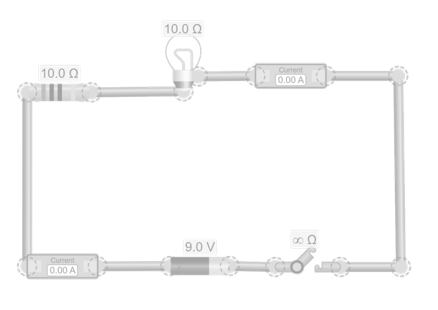
The ammeter: measuring current

The ammeter measures the current flowing through a conductor. To get a reading, it must be connected in series with the component you want to measure. In the simulation, just break the wire and place the ammeter in the path. Its display will show the current value in amperes.

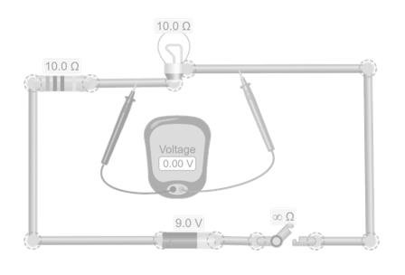
The voltmeter: measuring voltage

The voltmeter measures the voltage between two points in a circuit. To get a reading, it must be connected in parallel with the component you want to analyze—that is, its two terminals must be connected to the ends of the component. In the simulation, simply place the voltmeter’s terminals on those points, and the voltage value will appear on its display.

Important notes on measurement

To get accurate readings, it’s essential to connect the instruments correctly. The voltmeter must be connected in parallel, and the ammeter in series. If you reverse these connections, the circuit may stop working or show incorrect values. Also, remember that instruments are not neutral: even though this may not be noticeable in simulations, in real life they can affect the circuit if not properly designed or connected. That’s why learning to measure correctly is just as important as understanding what you’re measuring.

Explore the exciting STEM world with our free, online, simulations and accompanying companion courses! With them you’ll be able to experience and learn hands-on. Take this opportunity to immerse yourself in virtual experiences while advancing your education – awaken your scientific curiosity and discover all that the STEM world has to offer!

Simulations for measuring electrical quantities

Measuring current with the ammeter


Build a simple circuit with a power source, a light bulb, a resistor, and wires. Then place two ammeters at different points in the circuit. Observe the values shown on both displays. Are they the same? What does that tell you about the current? Now try changing the voltage of the power source. Do the ammeter readings change? Are they still equal?
Licencia de Creative Commons

Measuring voltage with the voltmeter


Use the same circuit as in the previous activity: a power source, a light bulb, a resistor, and wires. Now add a voltmeter to measure the voltage between two points in the circuit. To do this, connect its two terminals to the ends of the component you want to analyze—for example, the light bulb. Observe the value shown on the voltmeter’s display. What does that number mean? What happens if you switch the terminal positions? What if you measure the voltage at other points in the circuit, like across the power source?
Licencia de Creative Commons

To learn and experience

Take your knowledge to the next level with science kits and hands-on tools that connect theory with experimentation

“If I have seen further, it is by standing on the shoulders of giants”

Isaac Newton

Your path to becoming a giant of knowledge begins with these top free courses

Test your knowledge

Electrical quantities are the physical properties that describe the behavior of electricity in a circuit, such as voltage, current, and resistance. Measuring them accurately is essential because it allows us to understand the actual state of the circuit, identify possible faults, and ensure that devices operate safely and efficiently. These measurements are also the foundation for designing electrical systems, calculating energy consumption, and protecting both equipment and people from overloads or short circuits.
The relationship between these quantities is described by Ohm’s law, which states that the voltage across a conductor equals the product of the current flowing through it and its resistance. This relationship allows us to calculate any of the three quantities if the other two are known, and it is essential for designing electrical circuits, selecting suitable components, and diagnosing problems. Understanding this relationship also helps predict how the circuit behavior will change if voltage, current, or resistance values are modified, such as when the load increases or the conductor material changes.
Well, that usually happens because measuring instruments have their own limitations and precision, and real circuits are not always ideal. For example, the resistance of wires, temperature changes, and component connections can affect the measurement. It’s important to understand that a multimeter provides a very reliable approximation, but small discrepancies are normal and part of practical electrical work.
Yes, and this is directly related to Ohm’s law. If you keep the same voltage and increase the resistance, the current decreases; if you decrease the resistance, the current increases. This principle is essential for controlling current in circuits and protecting sensitive devices from overcurrent.
To measure voltage, current, and resistance correctly at the same time, instruments must be connected according to the type of measurement: the voltmeter in parallel with the component to measure voltage, the ammeter in series to measure the current through the circuit, and the ohmmeter across the component out of the circuit to measure resistance. Incorrect connections can alter readings or even damage the equipment, so it’s crucial to always follow proper measurement techniques.

You may also be interested

Electricityfrom the Noun Project
Cargando clima y ubicación...

You may also be interested