AC Power Source Combination
The online simulations of AC source combinations on this page allow you to immediately see how two alternating signals behave when they interact within a real circuit. To do this, we build two simple circuits—one in series and one in parallel—each with a light bulb as a visual indicator and the necessary instruments to measure what is happening. The voltmeter is always placed between the main nodes to display the voltage across the light bulb, while the ammeter is positioned at the appropriate point to record the current flowing through the circuit. From there, visitors can modify the parameters of the power sources and observe how the brightness, voltage, and current change, gaining a direct understanding of AC signal superposition without resorting to calculations.
This Thematic Unit is part of our Circuits collection

STEM OnLine mini dictionary
Beat
A dynamic phenomenon that appears when alternating current sources with slightly different frequencies are combined, characterized by a periodic fluctuation of the total amplitude that creates a visual modulation or envelope pattern.
Circulating current
An undesired electrical current that flows directly between two power sources connected in parallel when there is a mismatch in voltage, phase, or frequency, potentially causing instability or severe damage to the equipment.
Constructive interference
An effect that occurs when two or more alternating current waves coincide in phase or with minimal phase shift, causing their instantaneous amplitudes to add up and result in a signal with a higher total voltage or current.
Destructive interference
An effect that occurs when two alternating current waves are out of phase, causing their instantaneous amplitudes to subtract from each other, thereby reducing the total magnitude of the electrical signal or distorting its original shape.
Overlap distortion
An undesired alteration in the original geometric shape of an electrical signal within electronic circuits, produced when multiple alternating current waves interact unfavorably at a common node of the circuit.
Signal envelope
An imaginary curve outline connecting the peak and trough values of a complex or modulated waveform, making visible the periodic amplitude variation pattern caused by phenomena such as frequency beats.
Source combination
The connection of multiple alternating current generators within the same electrical circuit to analyze the superposition of their signals. The final output of voltages and currents depends simultaneously on the amplitudes, frequencies, and phase relationships of each source.
Source synchronization
A mandatory process in electrical engineering that involves matching the frequency, phase, and amplitude of two or more generators before connecting them in parallel. This prevents destructive circulating currents between the sources.
Vector signal summation
A mathematical and geometrical method used in electronics to combine alternating current signals, taking into account both the magnitude of the waves and their respective phase angles, rather than performing a simple arithmetic addition.
Wave superposition
A physical and electrical phenomenon where two or more sine waves combine at every instant of time within a circuit, resulting in a new composite waveform that can exhibit reinforcement, attenuation, or cancellation.
What is the combination of AC sources
The combination of AC sources involves connecting two or more alternating current sources within the same circuit to observe how their electrical effects add up. When multiple sources operate simultaneously, their voltages and currents do not simply add together: they depend on the amplitude, frequency, and, above all, the phase of each source.
In an AC circuit, each source generates a sinusoidal wave. When combined, these waves superimpose on one another and produce results that can be very different from those of each source individually: increases in amplitude, reductions, partial or total cancellations, and even periodic variations when the frequencies differ.
Understanding how multiple AC sources interact is essential for interpreting real-world phenomena such as interference, current sharing, beat frequencies, or unexpected behavior in electrical networks. Simulations allow us to visualize this superposition immediately and understand how small changes in phase or frequency completely alter the final result.
AC sources in series
When two AC sources are connected in series, their voltages add together according to the rules of superposition. However, this addition is not arithmetic: it depends on the amplitude, frequency, and phase of each source. If both waves are in phase, the resulting voltage increases; if they are out of phase, the combination may be reduced or even canceled out. In this configuration, the current flowing through the circuit is the same for both sources, so any difference in phase or frequency is directly reflected in the overall waveform. This allows us to observe phenomena such as constructive interference, where voltages reinforce each other, and destructive interference, where they cancel each other out.
Sum of voltages
When two AC sources are connected in series, their voltages combine according to the principle of superposition. The total voltage of the circuit is the instantaneous sum of the individual voltages, which means it depends on how the waves align at any given moment. If both sources have the same frequency and are in phase, the resulting voltage increases; if they are out of phase, the sum may be lower or even cancel out entirely.
Influence of phase
Phase is the factor that most determines the result of the combination. Two sources with the same amplitude and frequency can produce very different voltages depending on the phase difference between them. A small phase difference produces a reinforced signal; a large phase difference can reduce the total amplitude. When the phase difference reaches 180°, the voltages are completely opposed.
Constructive and destructive interference
Constructive interference occurs when waves reinforce each other, increasing the amplitude of the total voltage. Destructive interference occurs when waves cancel each other out, reducing the amplitude or distorting the waveform. In a series circuit, these effects are very clearly observed because the total voltage is the direct sum of both sources.
Cancellation due to phase shift
If two sources have the same amplitude and frequency but are out of phase by 180°, the resulting voltage is practically zero. Although each source continues to generate its own wave, the instantaneous sum cancels out. This phenomenon is particularly useful for understanding how phase can completely dominate the behavior of a circuit.
Effect of different frequencies (Beats)
When the sources have slightly different frequencies, the total voltage exhibits a characteristic pattern: beats. The amplitude appears to periodically increase and decrease, creating a visible envelope in the simulation. This effect arises from the difference between the frequencies and is a direct demonstration of how wave superposition produces dynamic phenomena even in simple circuits.
AC Sources in Parallel
Connecting two AC sources in parallel means connecting them between the same two nodes in the circuit. In this configuration, the voltage is common to all sources because they share exactly the same connection points. This implies that, in an ideal scenario, all sources should have the same instantaneous voltage, regardless of their internal characteristics. In practice, connecting different AC sources in parallel is not physically feasible unless they are perfectly synchronized. If each source attempts to impose a different voltage, enormous currents would flow between them, causing instability and potential damage. For this reason, in real-world installations, sources connected in parallel are used only when they are synchronized in frequency, phase, and amplitude—as is the case with generators in a power grid.
Sum of currents
In a parallel connection, each source attempts to impose its own current on the circuit. The total current is the instantaneous sum of the currents contributed by each source, and this sum depends on how the waves align at any given moment. If the sources are in phase, the total current increases; if they are out of phase, the sum may decrease or even be partially canceled out.
Influence of phase
Phase determines how the currents from each source interact. A small phase shift can alter the waveform of the total current, while a large phase shift can cause one source to “push” current in the opposite direction of the other. When the phase shift reaches 180°, the currents are completely opposite, resulting in a significant reduction in the total current of the circuit.
Constructive and destructive interference
Constructive interference occurs when the currents from both sources reinforce each other, increasing the total current. Destructive interference occurs when the currents cancel each other out, reducing the amplitude or distorting the waveform. In a parallel circuit, these effects are very clearly observed bec
ause each source contributes directly to the total current.
Cancellation due to phase shift
If two sources have the same amplitude and frequency but are out of phase by 180°, the total current can approach zero. Although each source continues to generate its own current, the instantaneous sum cancels out. This phenomenon is particularly useful for understanding how phase can dominate circuit behavior even when the sources are connected in parallel.
Effect of different frequencies (Beats)
When the sources have slightly different frequencies, the total current exhibits the phenomenon of beating: the amplitude of the current appears to periodically increase and decrease. The resulting envelope is clearly visible in the simulations and demonstrates how the superposition of waves with different frequencies generates dynamic variations even in simple configurations.
Real-World Applications of AC Source Combination
Although the combination of AC sources is studied under ideal conditions in educational circuits, the phenomena of superposition, interference, and phase shift constantly occur in real electrical systems. In power distribution networks, audio equipment, and electronic devices, different sources or signals interact with one another, producing amplifications, cancellations, or distortions of the waveform. Understanding these effects helps interpret behaviors that, at first glance, may seem anomalous but are a direct consequence of the superposition of alternating voltages and currents.
Interference in electrical grids
In an electrical grid, multiple generators operate in parallel to supply power. If they are not perfectly synchronized in frequency and phase, small differences may arise that cause interference in the voltage or current. These variations can manifest as fluctuations, harmonics, or waveform distortions, especially when large loads are connected or disconnected. Coordination among generators is based precisely on preventing their voltages from combining in an undesirable way.
Audio systems and signal mixing
In audio, the combination of AC signals is a constant occurrence. When two sound sources are mixed, their waves overlap and can reinforce or cancel each other out depending on their phase. This explains phenomena such as voice cancellation in some systems, phasing and flanging effects, or the occurrence of beat frequencies when two tones have closely matched frequencies. Although the context is acoustic, the mathematical behavior is identical to that of electrical sources.
Overlap in basic electronics
In electronic circuits, many AC signals are combined at common points: oscillators, modulators, filters, or amplification stages. The interaction between signals can produce interference, distortion, or amplitude variations that must be controlled to ensure the circuit functions correctly. Wave superposition is the basis for phenomena such as the vector sum of signals, the emergence of envelopes, or the generation of complex periodic patterns.

STEM OnLine mini dictionary
Beat
A dynamic phenomenon that appears when alternating current sources with slightly different frequencies are combined, characterized by a periodic fluctuation of the total amplitude that creates a visual modulation or envelope pattern.
Circulating current
An undesired electrical current that flows directly between two power sources connected in parallel when there is a mismatch in voltage, phase, or frequency, potentially causing instability or severe damage to the equipment.
Constructive interference
An effect that occurs when two or more alternating current waves coincide in phase or with minimal phase shift, causing their instantaneous amplitudes to add up and result in a signal with a higher total voltage or current.
Destructive interference
An effect that occurs when two alternating current waves are out of phase, causing their instantaneous amplitudes to subtract from each other, thereby reducing the total magnitude of the electrical signal or distorting its original shape.
Overlap distortion
An undesired alteration in the original geometric shape of an electrical signal within electronic circuits, produced when multiple alternating current waves interact unfavorably at a common node of the circuit.
Signal envelope
An imaginary curve outline connecting the peak and trough values of a complex or modulated waveform, making visible the periodic amplitude variation pattern caused by phenomena such as frequency beats.

Source combination
The connection of multiple alternating current generators within the same electrical circuit to analyze the superposition of their signals. The final output of voltages and currents depends simultaneously on the amplitudes, frequencies, and phase relationships of each source.
Source synchronization
A mandatory process in electrical engineering that involves matching the frequency, phase, and amplitude of two or more generators before connecting them in parallel. This prevents destructive circulating currents between the sources.
Vector signal summation
A mathematical and geometrical method used in electronics to combine alternating current signals, taking into account both the magnitude of the waves and their respective phase angles, rather than performing a simple arithmetic addition.
Wave superposition
A physical and electrical phenomenon where two or more sine waves combine at every instant of time within a circuit, resulting in a new composite waveform that can exhibit reinforcement, attenuation, or cancellation.
Explore the exciting STEM world with our free, online, simulations and accompanying companion courses! With them you’ll be able to experience and learn hands-on. Take this opportunity to immerse yourself in virtual experiences while advancing your education – awaken your scientific curiosity and discover all that the STEM world has to offer!
Simulations of AC source combinations
Series AC power sources
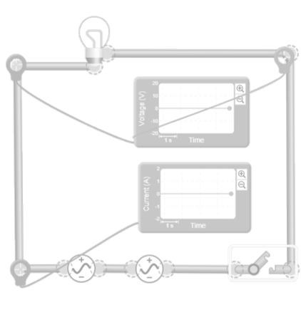
In this simulation, a circuit is constructed consisting of two alternating current sources connected in series and a light bulb located at the end of the circuit. The light bulb acts as an immediate visual indicator: when the voltage resulting from the combination increases, the brightness increases; when the combination is reduced or canceled out, the brightness decreases or disappears. This allows users to intuitively see how the sum of voltages behaves in a series connection. To allow visitors to measure what is happening, a voltmeter is placed across the terminals of the light bulb, so that it displays the total voltage generated by the superposition of both sources. In addition, an ammeter is connected in series with the circuit to record the current flowing through the light bulb and through both sources. With these two instruments, visitors can correlate the brightness with the actual electrical values.
The interactive activity involves adjusting the parameters of the power sources (voltage, phase, and frequency) and observing how the total voltage—and, consequently, the brightness of the light bulb—changes. When the power sources are in phase, the voltage is amplified and the light bulb shines brighter. When a phase shift is introduced, the resulting voltage decreases. If the phase shift reaches 180°, the light bulb practically goes out. If the frequencies are adjusted to be slightly different, the light bulb’s brightness rises and falls periodically, reflecting the phenomenon of beat frequency. The simulation graph shows how the resulting waveform matches what is displayed by the voltmeter, the ammeter, and the light bulb.
Parallel AC power sources
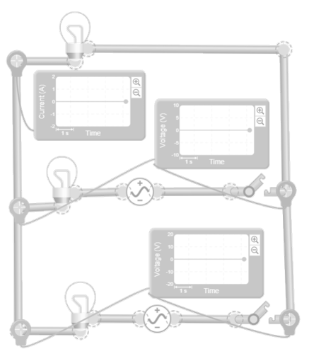
In this simulation, a circuit is built with two AC sources connected in parallel, sharing exactly the same two nodes. To visualize the effect of this combination, a light bulb is also connected between those nodes. Since the voltage is common to all branches, the light bulb acts as an indicator of the final result: if the currents supplied by the sources reinforce each other, the light bulb shines brighter; if they oppose each other, the brightness decreases. Although the voltages do not add up, the interaction between the currents modifies the power reaching the light bulb, and this is immediately reflected in its brightness. To measure what happens, a voltmeter is installed between the two main nodes, displaying the common voltage shared by the sources and the light bulb. In addition, an ammeter is placed on one of the branches, so that visitors can see the current supplied by each source and compare it with the total current flowing through the light bulb. This setup helps visitors understand that, in a parallel circuit, the voltage remains constant, but the currents do change depending on the phase and frequency of each source.
The interactive activity involves adjusting the parameters of the power sources and observing how the total current reaching the light bulb changes. When the power sources are in phase, both supply current in the same direction, and the light bulb receives more power, increasing its brightness. When a phase shift is introduced, part of the current from one source opposes that of the other, reducing the net current and causing the light bulb to dim. If the phase shift reaches 180°, the total current can approach zero, and the light bulb barely glows. If the frequencies are adjusted to be slightly different, the light bulb’s brightness rises and falls periodically, reflecting the beats in the total current. The simulation graph allows you to correlate these changes with the actual waveform flowing through the light bulb.
Giants of science
“If I have seen further, it is by standing on the shoulders of giants”
Isaac Newton
Michael Faraday
–
André-Marie Ampère
–
Become a giant
Principles of Modeling, Simulations, and Control for Electric Energy Systems
Principles of Electric Circuits | 电路原理
Electrotechnique I
Electromagnetic Compatibility Essentials
Professional development for Educators
How to Learn Online
Assessment Design with AI
Introduction to Data Wise: A Collaborative Process to Improve Learning & Teaching
Chatbots for Instruction
Giants of science
“If I have seen further, it is by standing on the shoulders of giants”
Isaac Newton
Michael Faraday
–
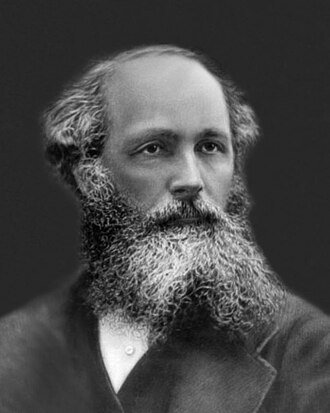
James Clerk Maxwell
–
Become a giant
Principles of Modeling, Simulations, and Control for Electric Energy Systems
Principles of Electric Circuits | 电路原理
Electrotechnique I
Electromagnetic Compatibility Essentials
Professional development for Educators
An Introduction to Evidence-Based Undergraduate STEM Teaching
Get started with teaching computing
What Works in Education: Evidence-Based Education Policies
Teach teens computing: Databases and SQL
Test your knowledge
What does it mean to combine alternating current sources and why isn’t the result a simple sum?
How does phase influence the combination of AC sources and why is it the most decisive parameter?
Why can two AC sources in series cancel each other completely even though both are operating?
Why can connecting unsynchronized AC sources in parallel be dangerous?
What are beat phenomena and why do they appear when sources have slightly different frequencies?
You may also be interested
Last simulations
To learn and experience
Take your knowledge to the next level with science kits and hands-on tools that connect theory with experimentation
Calculadora científica

Essential for teachers and students
Notion
Organize your notes, tasks, and projects in one place. Notion combines notes, lists, and calendars in one flexible space.
Canva
Design presentations, diagrams, and infographics with easy-to-use templates and professional results
Genially
Create interactive content, presentations, and educational games in a simple and visual way
Desmos
The most intuitive graphing calculator to explore mathematics and create dynamic classroom activities
Tinkercad
Design in 3D and simulate electronic circuits for free; it’s the perfect tool for simple robotics projects
Your Infinite Library
Enjoy the freedom to explore millions of titles and a curated selection of magazines on any device
Join Prime for students and young adults
The best series. Millions of songs. All included with your subscription.
Science made fun
Learn with the best courses
40% off!
Coursera
Courses from leading universities and companies. Learn practical skills and earn professional certifications
edX
Online courses from leading universities and companies. Learn practical skills and earn professional certifications
Udemy
Thousands of online courses tailored to your level. Learn at your own pace with expert instructors